Lab 5
Prelab
In order to simplify debugging, I first determined the method I would use to send and recieve data over Bluetooth. To accomplish this, I initialized three Arduino cases.
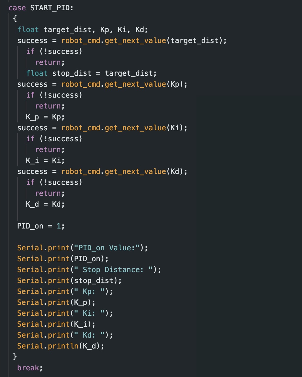
1. START_PID
This case clears all previous data, starts my front ToF sensor, initiates storage of time data, and sets PID_on to true (this is initialized as false to keep the car off until the command is called). For the START_PID case, the command inputs consist ofthe desired end distnace from the wall (target_dist), as well as the three controller values (Kp, Ki, and Kd).
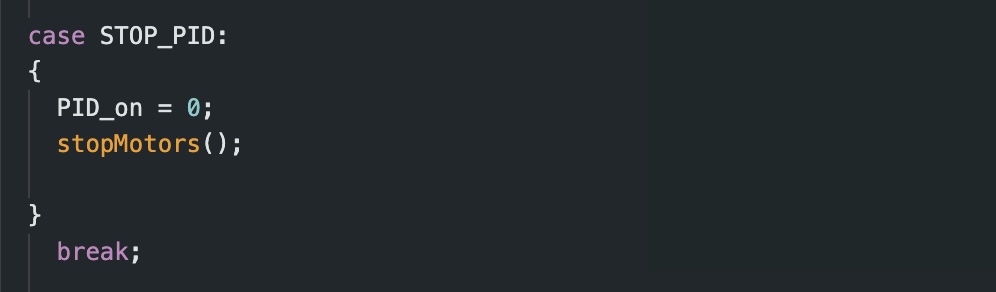
2. STOP_PID
This case resets PID_on back to false and stops the motors from running.
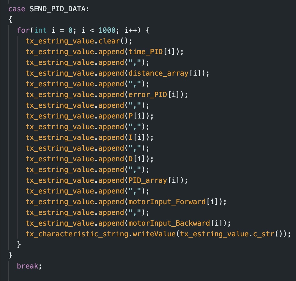
3. SEND_PID_DATA
This case transmits the collected PID data to my computer via Bluetooth. While designing the SEND_PID_DATA case, I decided that the relevant information that I needed to send to Jupyter Notebook consisted of: time, distance (inches), error, P, I, D, and PID values, as well as the motor input.
I called these commands through the following code in Python:

(Note: I did not call the STOP_PID command because I implemented a seperate stopping mechanism which stops the robot once the amount of data collected exceeds the size of the array it’s being stored in)
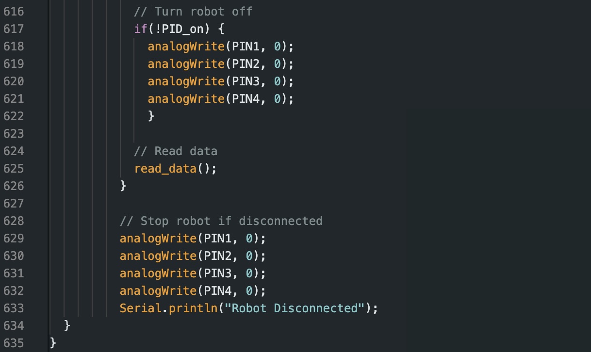
Additionally, I implemented a hard stop feature into my code such that if the Bluetooth connection fails, all pin values will be set to 0. Once my code is outside the while loop I have for “central.connected()” (indicating that the Artemis board is no longer connected) the robot will come to a complete stop.
Lab Tasks
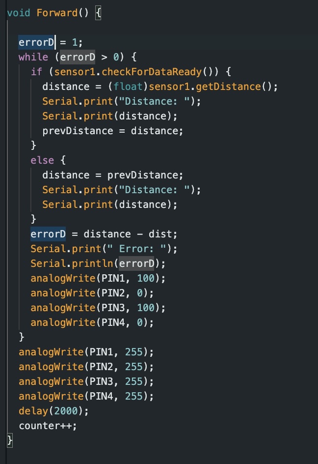
Before implementing my PID controller, I ran some preliminary tests to see how my robot would perform with the task. To do so, I combined my codes from labs 3 and 4 to create a simple code which would drive the car forward at a set speed until the front ToF sensor detected a distance of 1 foot from the wall. My car immediatly slammed into the wall.
Position Control
For this task, I implemented PID control such that it can adapt to changing conditions such as starting distance from the wall. I wrote code in my loop function that is continously checking the status of PID_on which can either be set to 0 or 1 (off or on). When set to 1, the robot starts collecting data, and moving.
Sampling Frequency of ToF sensor
By implementing a simple, temporary code into my Arduino script, I was able to calculate the average sampling rate of the ToF sensor. I accomplished this by finding the time difference between each new measurment from the ToF sensor. By using the millis() function to track time, I was able to use a variable deltaT to track the difference in time between each ToF reading.
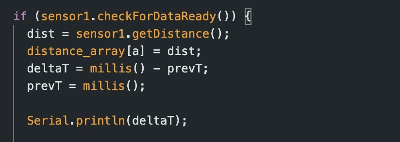
I found that my ToF sensor had a sampling period of 100ms. By implementing a similar method into my PID control loop, I was able to find the sampling rate for that as well. From this I found that my PID loop runs much faster than my ToF sensor can collect data. My loop runs ar roughly 10ms which is 10x faster than my ToF sensor. I will acknowledge this disparity later.
Proportional Control
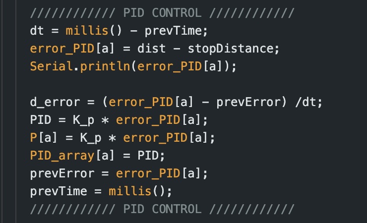
I started by implementing proportional control and troubleshotting the ideal Kp value for my robot. For the P controller, my robot adjusts its movement depending on its distance from the goal of one foot. Based on this, it will either move forward (or backward if it overshoots) at a corresponding PWM. The output speed is dependent on the error (the distance read by the ToF sensor - the goal distane) and the Kp value.
The movement of the car was determined by two functions driveForward_PID and driveBackward_PID. These two functions (shown below) set the motor speed and direction depending on the PID value and ensured that the value was within bounds.

As a starting value, I set my Kp value to be 0.1. I conduted multiple tests with different Kp values to find the optimal value for my system. At Kp = 0.1, my robot would hit the wall well before it started reversing. Below is a video of that occuring:
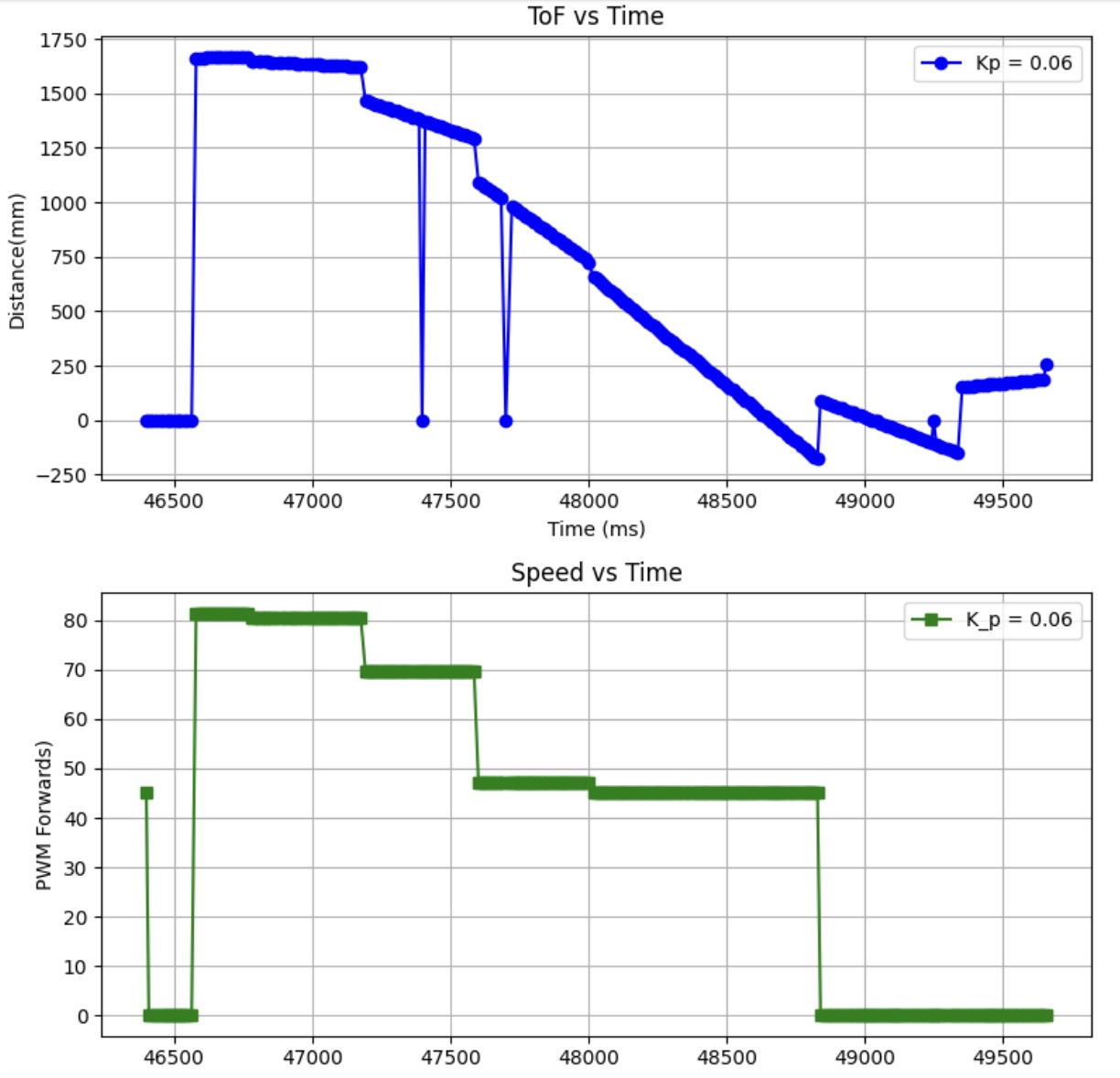
At Kp = 0.06 my robot managed to stop however it was just shy of hitting the wall before it began to reverse. Below is some of the data I collected from that trial:
After multiple trials, I found that the optimal value was Kp = 0.01. This yielded the best results with my robot stopping at roughly 300 mm away from the wall. While I couldn’t get the exact positioning with the P control, I found that this was a good foundation for me to move on to PD control.
Derivative Control
Once I found a good value for Kp, I moved on to refining my Kd value such that I could implement P and D control simultaneously. Given the tendency of my robot to overshoot and oscillate heavily before stopping at its destination, I started with a higher Kd of 3.
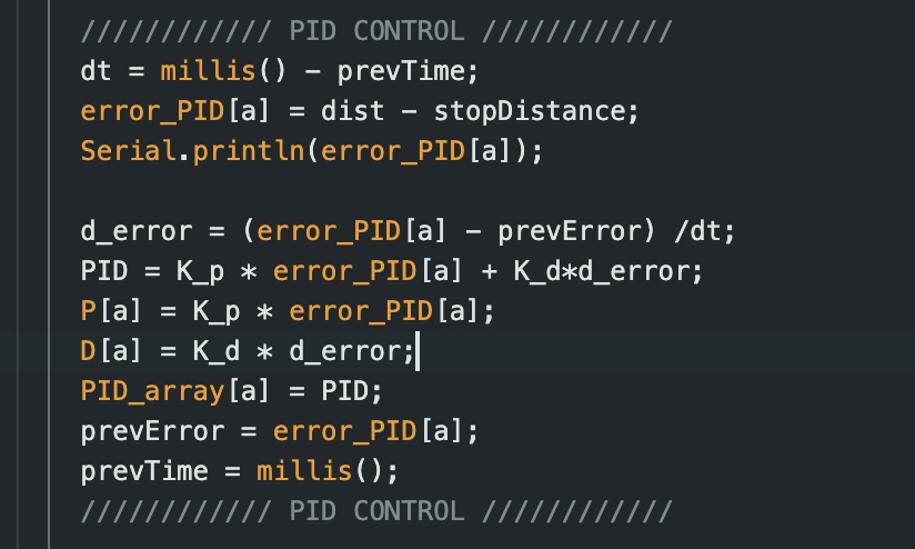
I adjusted my code by accounting for Kd in my PID value, as well as collecting D values in a seperate array.
Linear Extrapolation
To account for the disparity between my ToF sensor and my PID loop, I used the standard extrapolation equation:
y = y1 + (x - x1)((y2 - y1)/(x2 - x1))
I implemented this into my code by adding an else if statement which checks if my ToF sensor has a new reading. If thre is a new reading, it is added to the distance_array like normal. However, if there is not a new reading, the former two measurements are recorded and used to exrapolate a new value based on their average.
References:
For this lab, I referenced the lab reports of Mikayla Lahr, Daria Kot, and Stephen Wagner. I used ChatGPT to help trouble shoot with issues in my code that arose.